League City sits on the Gulf Coastal Plain, where the near-surface geology is dominated by Pleistocene-age Beaumont Formation clays. These stiff to very stiff, overconsolidated clays are notoriously expansive. The seasonal moisture fluctuation here—with annual rainfall exceeding 50 inches—creates significant shrink-swell cycles. We see active zone depths routinely reaching 8 to 12 feet below grade. For any retaining wall design in League City, ignoring this expansive potential leads to excessive lateral earth pressures. Our laboratory determines the specific swell pressure and soil suction profiles needed for rational wall design. We run the ASTM D4546 swell tests and D5298 suction measurements on undisturbed Shelby tube samples. This data feeds directly into the lateral earth pressure diagrams, moving beyond generic at-rest assumptions to a profile calibrated for the actual soil mineralogy—often smectite-rich clays with PI values exceeding 35. Before setting the wall geometry, a slope stability analysis of the proposed cut is necessary when the retained height exceeds 6 feet, especially near Clear Creek and its tributaries.
A retaining wall in League City's Beaumont clay isn't just a concrete cantilever—it's a moisture management system. The drain is as important as the steel.
Local considerations
ASCE 7-22 and the adopted IBC place League City in a region where both wind and seismic loads interact with retaining structures. The design must check the seismic earth pressure increment (delta_Pae) using the Mononobe-Okabe method. Our geotechnical report provides the peak ground acceleration (PGA) and site class for the specific parcel—often Site Class D due to the stiff clay profile. The greater risk, however, is water. A poorly drained wall in the Beaumont clay develops hydrostatic pressure that doubles the total lateral thrust. We've observed walls leaning 3 to 5 degrees outward within two years of construction due to clogged drains. The expansive backfill pushes the stem and shrinks away, creating an open fissure that channels surface water directly behind the wall. This cycle accelerates failure. We mitigate this with a capillary break and a compacted clay cap at the surface, sloping away from the wall. For walls over 10 feet high, we require instrumentation—inclinometer casings behind the stem and survey monuments on the face—to monitor performance during the first wet-dry cycle. The IBC 1807.2.3 requirement for a geotechnical investigation is not a formality here; it's the only way to capture the site-specific swell and drainage conditions that dominate wall performance in this part of Galveston County.
Frequently asked questions
What type of retaining wall works best in League City's clay soil?
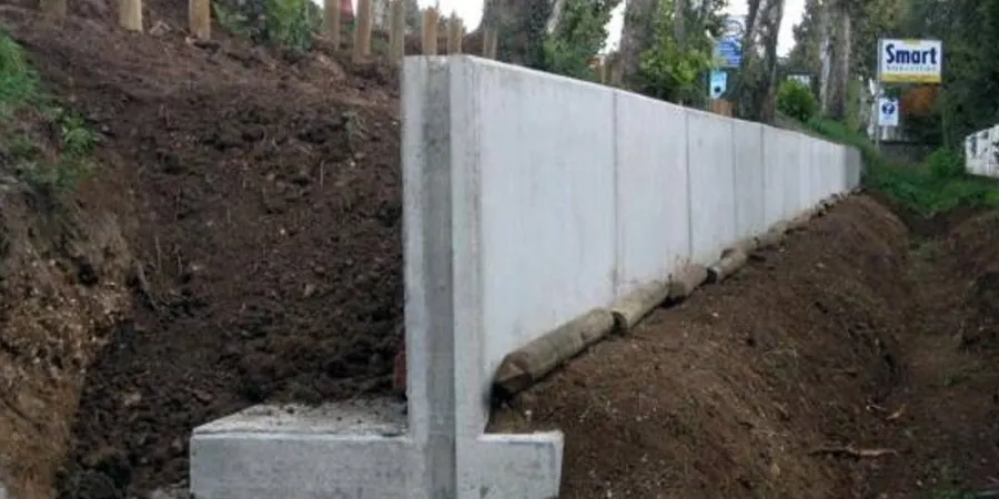
Cantilever reinforced concrete walls and mechanically stabilized earth (MSE) walls perform well if the backfill is properly specified. The key is using a non-expansive select fill in the reinforced zone and a free-draining aggregate behind the wall. We run swell tests on the native soil to determine the required backfill width, typically a zone 2 to 3 feet wide directly behind the stem for cantilever walls.
How deep do retaining wall footings need to be in League City?
The embedment depth is governed by the active zone of moisture fluctuation and global stability requirements. In League City, we typically recommend a minimum embedment of 2.5 to 3 feet for walls under 6 feet high, and deeper for taller walls. The footing must sit below the depth of seasonal cracking. We determine this from the soil suction profile measured with filter paper per ASTM D5298.
Do I need a geotechnical report for a retaining wall permit in League City?
Yes. The City of League City adopts the IBC, which in Section 1807.2.3 requires a geotechnical investigation for retaining walls supporting more than 4 feet of unbalanced fill, or supporting surcharge loads. Our report provides the soil parameters, bearing capacity, lateral earth pressures, and drainage recommendations that the structural engineer needs for the permit submittal.
What is the cost range for retaining wall design and soil testing in League City?
For a typical residential or commercial retaining wall project in League City, the geotechnical investigation and design parameter report ranges from US$1.150 to US$3.820. The final fee depends on the wall height, the number of borings required, and the specific laboratory tests needed—such as direct shear or swell testing.
How do you handle the high groundwater table near Clear Creek for wall design?
We install a piezometer during the field investigation to measure the static water level. The design includes a continuous toe drain consisting of a perforated pipe in a gravel chimney, wrapped in geotextile. The backfill directly behind the wall is a clean, free-draining granular material. We calculate the pore pressure profile and include it in the lateral earth pressure diagram. The drain must daylight to a positive outlet or connect to a storm sewer.